How do computers render 3D graphics?
A brief rundown on some of the core concepts that takes games from a bundle of numbers to a full
3D experience.
This Blog post was adapted from my video on the same topic here.
Introduction
How does the computer work?
It’s a question I frequently ask myself. Unfortunately it’s a big question and I don’t know the answer yet. I can however try to narrow down my question to something a bit more specific.
How does the computer make Elden Ring go?
Even more specifically how does it project 60-ish 3D images to my 2D screen with all its shading and textures and lights?
In this blog post I will be trying to figure out just this. We’re gonna look on a super low level at what exactly is happening behind the scenes in a graphics API such as OpenGL or Vulkan.
Essentially I want to take you from maybe knowing nothing about how graphics are drawn to your screen to maybe knowing something about how graphics are drawn to your screen.
First things first a few basics. In 3D graphics we aim to render, which is the process of drawing a 3D object onto your screen, meshes onto our screen. You can think of meshes as essentially a list of 3D points each with an X, Y, and Z value called vertices. We aim to color in between the vertices with the correct textures and shading to render our mesh.
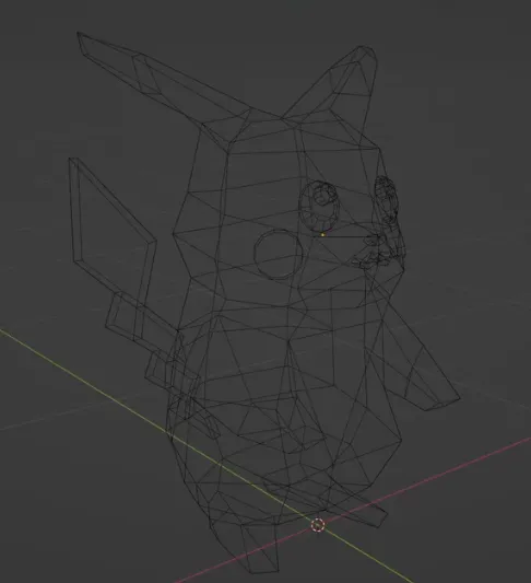
Okay so let’s get started. The first thing we might want to figure out how to create is a wireframe render like this:
Bresenham's Line Algorithm
To do this we need to figure out how to join our vertices with lines. Introducing Bresenham’s line algorithm.
Bresenham’s line algorithm will figure out exactly which pixels need to be colored between two 2D points on our screen from (x1, y1) to (x1, y2) and don’t worry we will come back to the third Z point later.
We’re also going to use a few assumptions about the line:
- The line is going from left to right and bottom to top and the gradient is between zero and one.
Essentially we want our algorithm to loop through every X pixel, determine the Y value and then color the pixel accordingly to find the Y value of our next pixel.
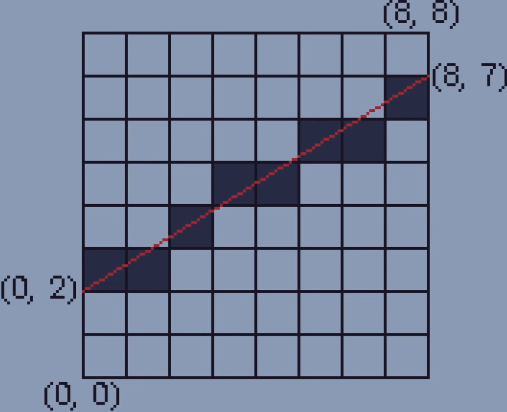
For the first step, there are two options of pixels we can draw. We can either pick the pixel to the right of our current pixel or we can pick the pixel to the top right of our current pixel. But how do we choose? We can use a variable called the error to determine which option to pick. The error is essentially how far away the actual line is away from the center of the pixel on the screen. We calculate this by taking the Y position of the line and subtracting the Y value of the next pixel.
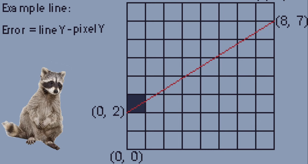
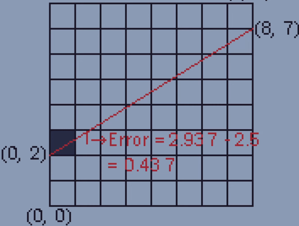
We check the error for the pixel to the right of our current pixel and if the error is larger than one half, we go to the top right. If the error is less than one half it’s best to just go right.
So in this example the error is less than one half so we just fill the pixel to the right.
But in this example the error is more than one half, so we fill the pixel to the top right.
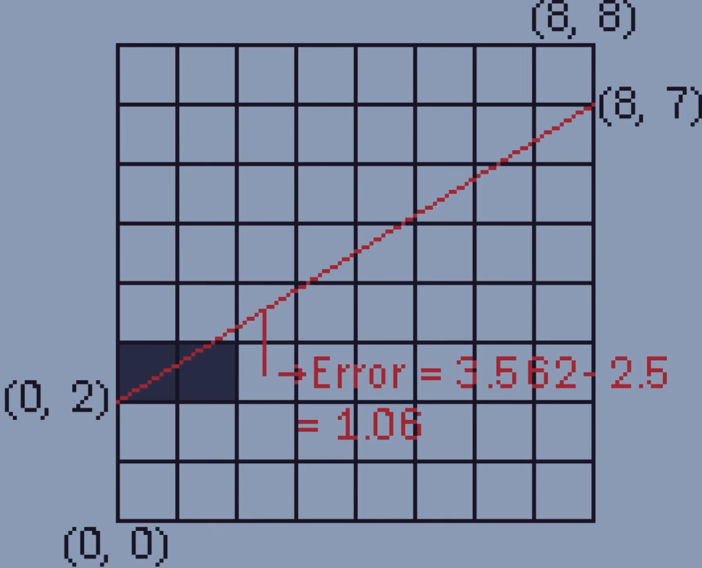
Now we know where to draw the next pixel for each point in our line so we can just do it over and over again until the line is complete.
One important thing about the algorithm is that it uses only additions and subtractions to calculate all this making it faster than other algorithms which use more expensive divisions.
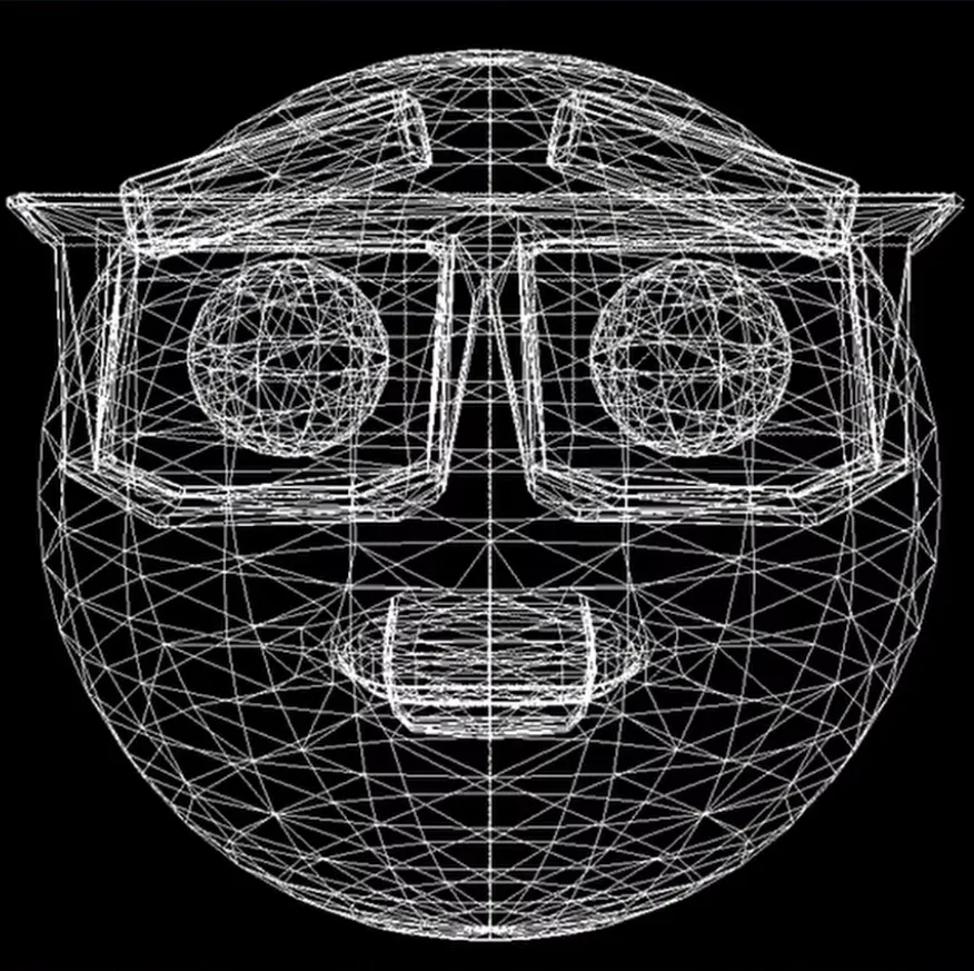
Now if we apply the algorithm for all the X and Y vertices in a mesh ignoring the Z axis, we get this:
Rasterisation
Next up, we need to figure out how to fill these triangles in. Unfortunately that is easier said than done.
To understand this we will start with just one triangle that has the points A, B, and C. We can start by just drawing lines between each point using the algorithm.
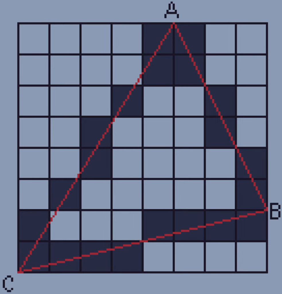
In order to fill in the triangle we’re going to need to start by saving all the pixels on our lines in a list.
To do this we will save each X position with the same Y position. So for Y8 there are two pixels, at X5 and X6. For Y7 there are also two pixels, at X5 and X6. For Y6 there are two pixels at X4 and X7 and so on and we have done this for all of our pixels.
Once we have all of our lists of X values we can save all of these in one big array. We can now access all of the X-coordinates around the edge of the triangle with their associated Y-coordinate. This makes it super easy to fill in our triangle using the line algorithm. All we have to do is draw a line between the first and last X-coordinate for each Y-value.
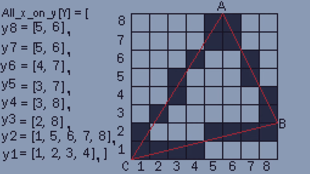
So for the first line Y8 we draw a line between the coordinates (5, 8) and (6, 8) which doesn’t actually do anything because there isn’t a gap. Same for the pixels we draw at Y7. For Y6 we draw between the coordinates (4, 6) and (7, 6) which fill in two pixels. We just carry this on until the triangle is filled.
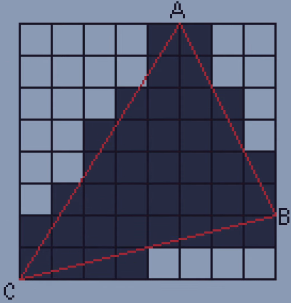
This algorithm is called the line sweep algorithm because it sweeps down each triangle from top to bottom. There are many other techniques which are used to rasterize triangles and I’m sure others are much faster but this one was definitely the easiest for me to understand.
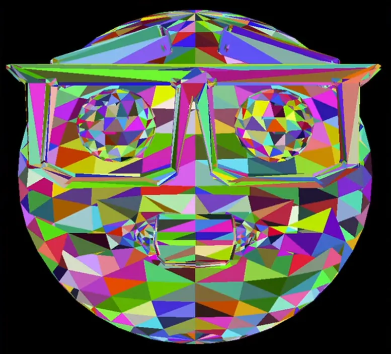
Cool, so now we know how to draw a single triangle we can just do this for all of the triangles in our mesh.
Shading
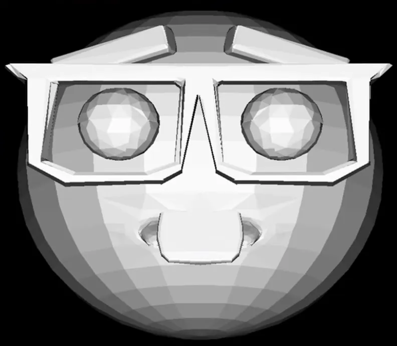
Okay so at the minute all of our triangles are just being given a random color but we might want to figure out how to shade our triangles using flat shading.
Flat shading is where each polygon’s color depends on its direction from the light. Here’s the basic rule with shading:
At the same light intensity each polygon is illuminated most brightly when it is facing the direction of light.
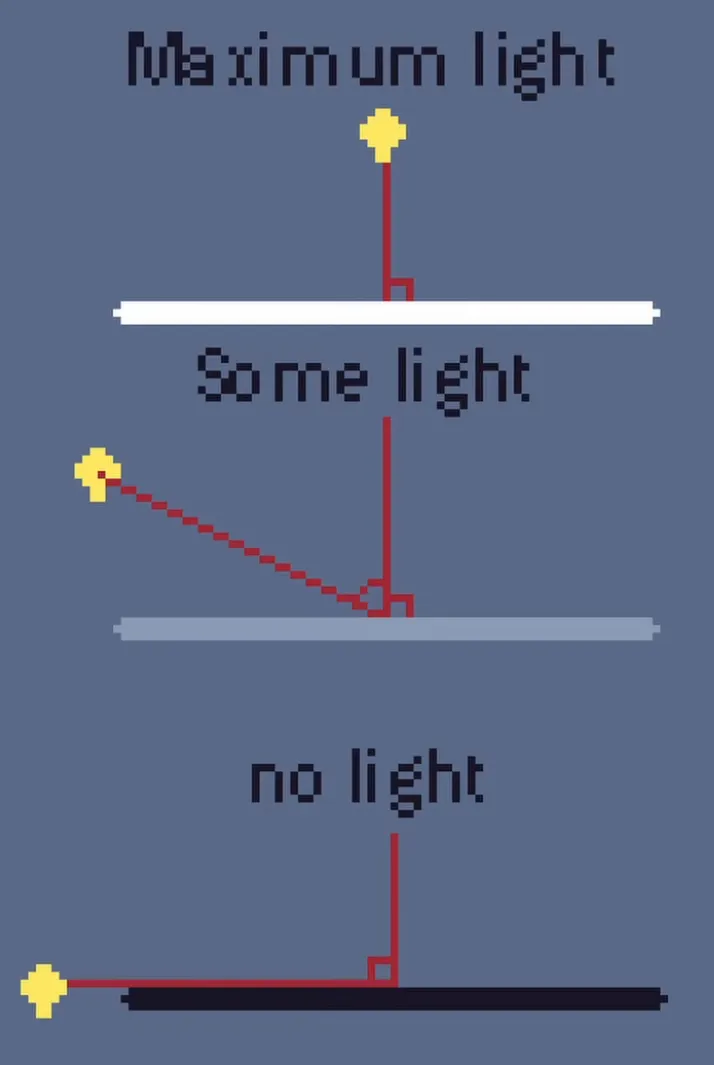
Essentially if I hold a light directly in front of a flat surface it will be at its brightest, but if I hold a light directly to the side of a flat surface it will get no illumination. If I hold it at an angle it will be somewhere in between.
One great bonus of this is that if our light intensity value is negative it means that the light is coming from behind the polygon and therefore the polygon is invisible. Since we don’t need to render invisible things we can just simply delete them before we actually render them. This technique is called backface culling.
Hidden Face Removal
You can’t see it on this model since it’s convex but for concave models, you would see artifacts where triangles are not drawn in the correct order. The polygons are still drawn to the screen since they still face the correct direction and therefore the back face culling doesn’t affect them but there’s nothing to tell the computer not to render them because they’re behind other polygons, like on this guy's mouth.
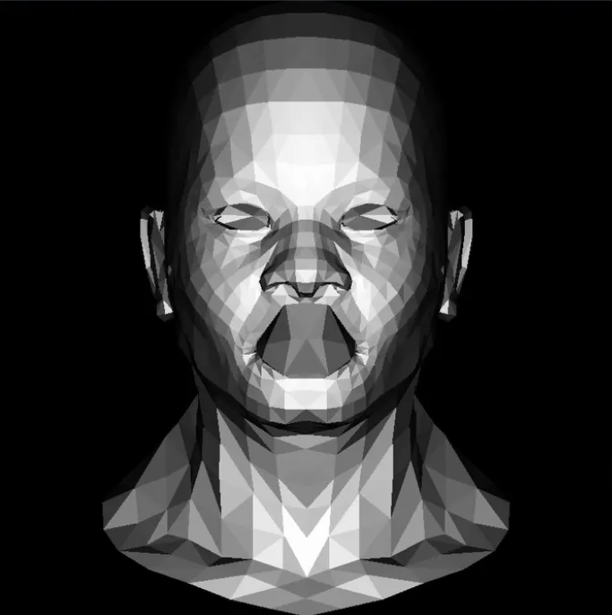
Luckily there’s a fix to this with a process called hidden face removal which requires something called the Z buffer. This technique will stop the computer from drawing polygons on top of one another.
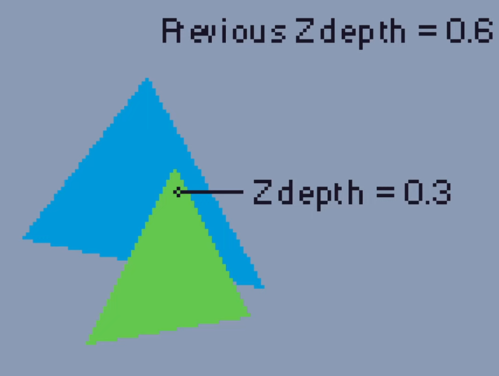
The Z buffer is a two-dimensional array that stores the Z value of each pixel. It can be displayed as a texture often called a depth texture where the darker a pixel is the further away it is from the camera.
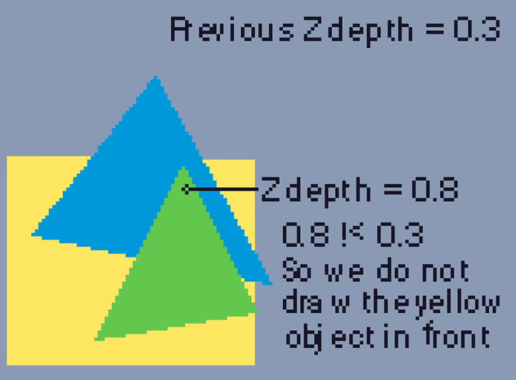
The computer can check the Z value of each pixel as we render each polygon. If the Z value for a pixel is smaller than the current Z value it means that the new pixel is in front of the previous one so we want to draw the new pixel to the screen.
For example, this green triangle Z depth is smaller than the Z depth of the blue triangle, so we draw it in front of the blue triangle.
However if there is a third triangle with a Z depth larger than the previous Z depth it means that it’s behind those polygons and so we don’t draw it in front. Just like this yellow square is behind the blue and green triangles.
This helps fix our issues with concave shapes as all of our hidden faces are removed.
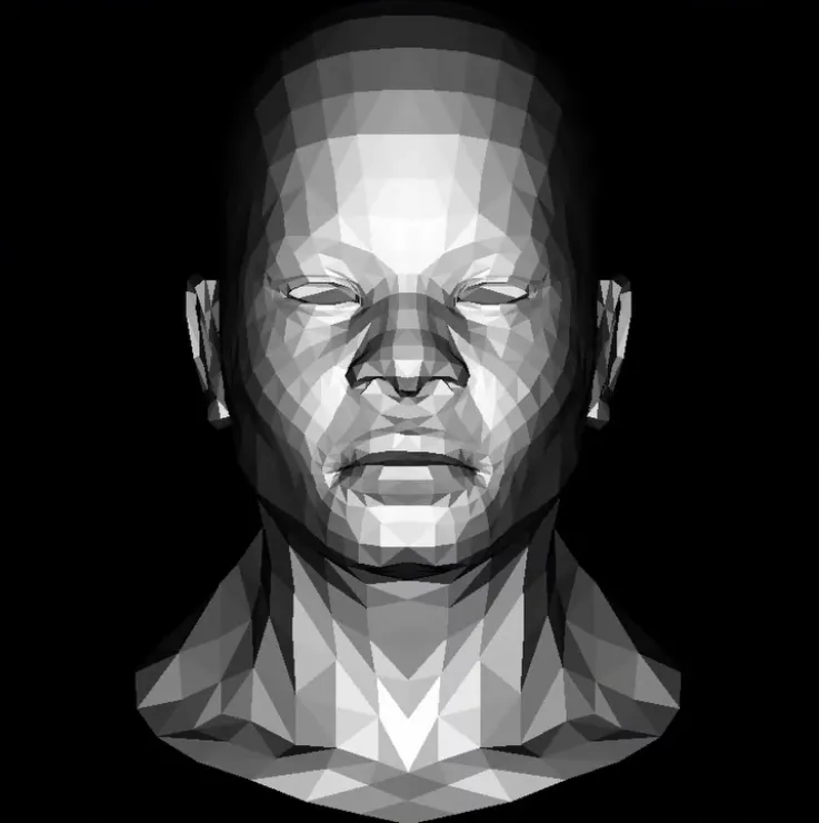
Okay so at this point we might feel satisfied with what we have.
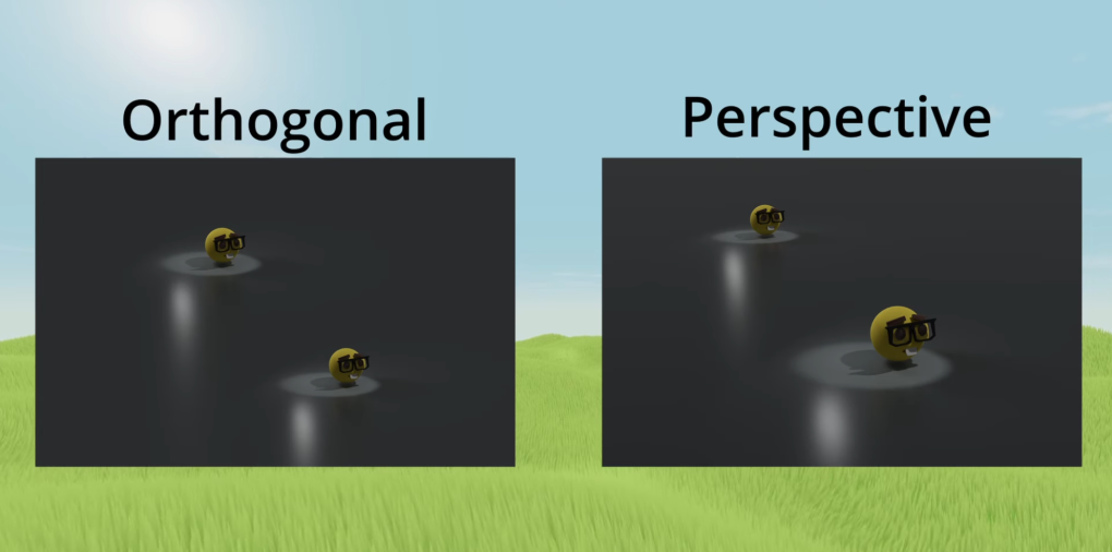
If you are you shouldn’t be because we have completely forgotten about the third dimension until this point (except for in the Z buffer where we did use the third dimension). That’s right folks all of these triangles which we’ve been rendering have been 2D. We have quite literally just taken the X and Y coordinate for our model and just forgotten about the Z. Essentially what this means is that the image on our screen is an orthographic view and has no depth at all. We want it so that things further away from the camera will appear smaller just like in real life.
In order to do this we need to apply some perspective.
Perspective Projection
To apply perspective we need something called a frustum. This is a shape which we view all of our objects inside of.
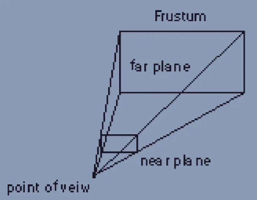
It has a near plane, which is what we project our objects onto (think of this as the screen), and a far plane, anything past the far plane will not be rendered.
To project the object in 3D space we would use the projection matrix. This can be rather complicated and it’s a bit beyond this blog post so I’m going to simplify it with an example in 2D, where we’re going to figure out how to project onto our 1D near plane.
Let’s have a look at our example where Ys is going to be the perceived height of our tree on our near plane from the viewpoint.
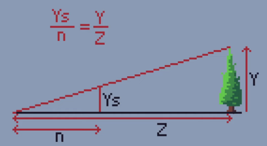
We know that the side lengths of both the small and big triangle are proportional to one another so in order to find Ys we can use the following equation. This shows that the apparent height of the tree, Ys, is equivalent to the distance to the near plane, n, multiplied by the object’s true height, y, and then divided by the distance to the object which is Z.
Let’s imagine a more simple example where we want to find out where this point would appear on our near plane from the camera’s position at the origin. We use the camera’s distance to the near plane which is 2 in our case and multiply it by the object’s true height, which is 3.5, then we divide it by the distance to the object and we find our perceived height is 1.
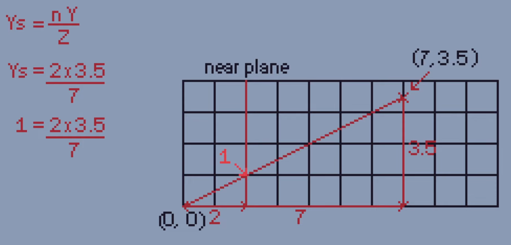
If we check this by drawing a line, yep, 1.
So in order to do this in a game we would literally just do this for every vertex on every object on our screen.
Awesome!
And here’s a comparison of the two projection types in the scene with a lot more depth just to drive home how much of a difference this makes.
Outro
I just want to give a massive thanks to Dmitry V. Sokolov and the Tiny Renderer projects for providing these amazing resources for free. They’re amazing to learn from and I highly recommend going through their lessons if you want to know more.
And there you have it, some of the basic concepts for rendering objects in 3D!
Resources:
- Line rendering
- Flat shading
- How the Z buffer works
- Tiny Renderer project
- 3D perspective projection
- Thanks to Kevin Who for some help with proofreading and fact-checking.